Nesting arranges your flat parts onto sheets of material for your future CAM use. This article covers how to prepare your geometry, set up a nest, choose the right node, read the results, and send the layout on to cutting.
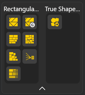
The plugin packs a set of parts onto one or more sheets and returns the arranged layout along with the data you need to cut and reassemble the parts. Its nodes are organized into two groups:
Rectangular Nesting packs parts using their bounding boxes. Fast and well suited to rectangular or regular parts.
True Shape Nesting packs the real outline of each part, which saves material on irregular shapes.
Each node takes the same core inputs (your parts and your sheet size) and returns the same core outputs (the placed parts plus tracking data), so once you have learned one node, the rest work the same way.
Nesting is a 2D operation. It arranges flat parts on a flat sheet, so your geometry has to be ready for that.
Flatten your parts. All the geometry you feed into a nesting node should be flattened onto a single plane. If your parts sit in 3D or at different heights, flatten or project them down first so the node sees clean 2D profiles. Parts that are not flattened will not nest correctly.
Set the Origin if needed. The Origin input controls where the nested layout appears in the scene. By default it sits at [0, 0, 0].
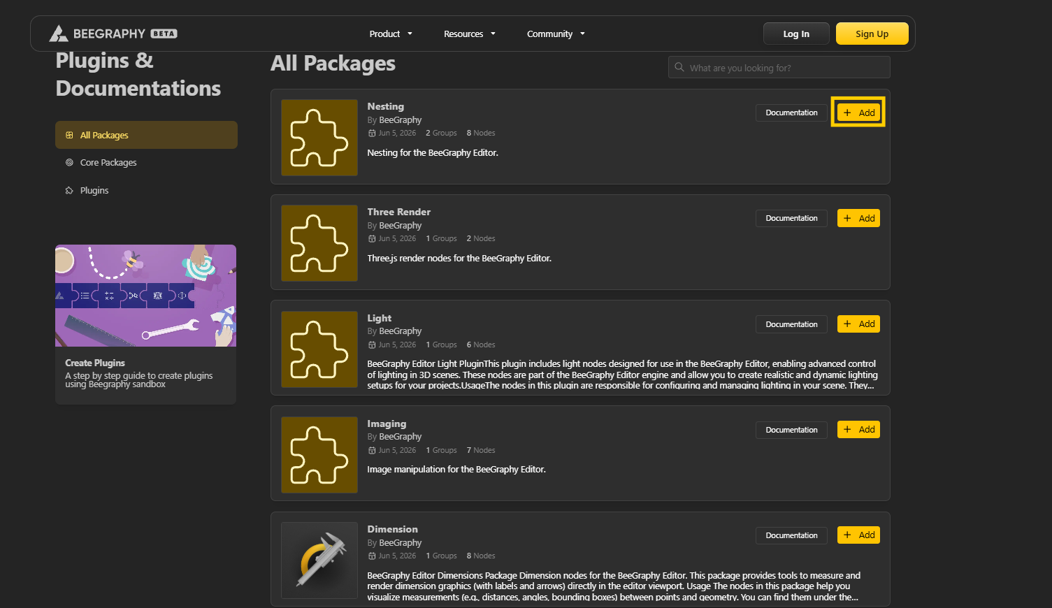
Navigate the page and find the Plugin you want to Add. Select + Add to add the Plugin in your workspace editor.
Open / Refresh Workspace Editor and find your recently added plugins in the toolbar menu.
From the node menu, Drag the node you want onto the canvas.
Flatten your parts: Use Flatten Tree Node to help you flatten your geometry so that each of your node is a separate piece.
Place a nesting node (see "Choosing the right node" below if you are not sure which).
Connect your parts to the node's Geometries input.
Set the sheet size: Enter your real stock dimensions in Sheet Width and Sheet Height.
Set Spacing to your kerf.
Tune the optional controls if the node has them (see the inputs reference below).
Check the result. Read the outputs, and make sure no part came back with a Sheet ID of -1, which means it did not fit.
Pick your node based on what your cutting machine can do, then on how much computing time you want to spend.
If your machine only makes straight, edge-to-edge cuts (panel saws, beam saws, glass tables, format cutters), use a guillotine node:
Guillotine Best Fit for a fast straight-cut layout.
Genetic Guillotine Best Fit for a tighter straight-cut layout, at the cost of more compute.
Guillotine 3-Stage if your machine is a format cutter that works in strips and stacks.
If your machine can follow any path (laser, waterjet, plasma, CNC router, knife or drag cutters), you have more options:
Row Naive for an instant, orderly preview while you design.
BLF Naive and CBLF Naive for quick free-placed layouts.
MaxRects Best Fit for a stronger free-placed layout of rectangular parts.
Polygon Genetic for irregular parts, where it packs real outlines, rotates them, and fits small parts inside the holes of larger ones.
Every nesting node shares the same core inputs:
Origin (default [0,0,0]): where the nested layout is placed in the scene.
Geometries: the parts to nest. (Flatten these first, see above.)
Sheet Width / Sheet Height (default 500 each): the size of your stock material.
Spacing (default 0): the gap kept between parts. Set this to your kerf, the width your blade or beam removes, so the layout accounts for it.
Edge Clearance (default 0): the margin kept clear around the sheet edge, your trim allowance.
SheetsGap (default 10): spacing between multiple result sheets in the output view only. It does not affect the material.
Some nodes add extra controls:
Num Cursors (CBLF Naive, Guillotine 3-Stage): how many arrangements to try before keeping the best. Higher packs tighter but runs slower.
Seed (CBLF Naive, Genetic Guillotine, Guillotine 3-Stage, Polygon Genetic): locks in the node's randomness so you get the same layout every run. Change it for a fresh attempt.
Allow Rotation (Guillotine 3-Stage): on/off switch for flipping parts 90 degrees.
Rotation Steps (Polygon Genetic, default 4): how many angles to test. 4 means 0, 90, 180, 270; higher tests finer angles.
Min usable size (Genetic Guillotine, default 50): the smallest a leftover piece can be and still count as a reusable offcut.
Curve Tolerance (Polygon Genetic, default 0.1): how closely the packer follows curved outlines, in mm. Tighter is more accurate, looser is faster.
Every node returns the same set of outputs:
Sheets: the boundary rectangle of each sheet used. Count them to see how much stock the job needs.
Geometries: your parts moved into their final nested positions.
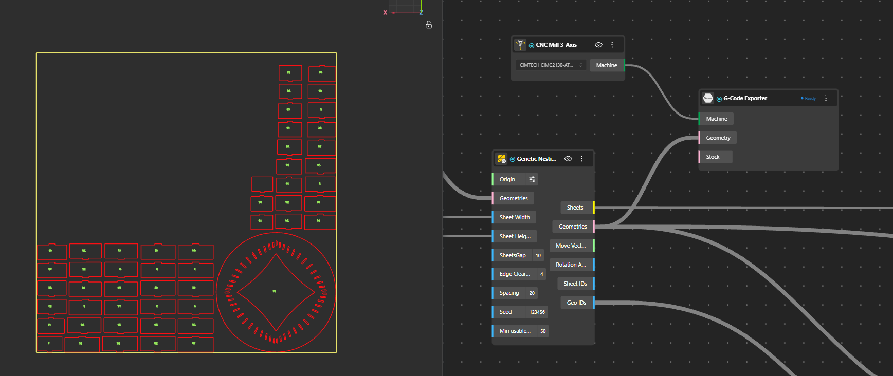
Move Vectors and Rotation Angles: the exact shift and turn applied to each part. These line up with your input order, so you can reapply them to your original model and keep each part's material, IDs, and colors intact.
Sheet IDs: which sheet each part is on. A value of -1 means the part did not fit, so this is your overflow check.
Geo IDs: the original input index of each part, so every cut piece traces back to its place in the model.
Note: the plain Guillotine Best Fit node does not output Rotation Angles; every other node does.
Once your parts are nested, BeeGraphy can take the layout the rest of the way to your machine without leaving the editor.
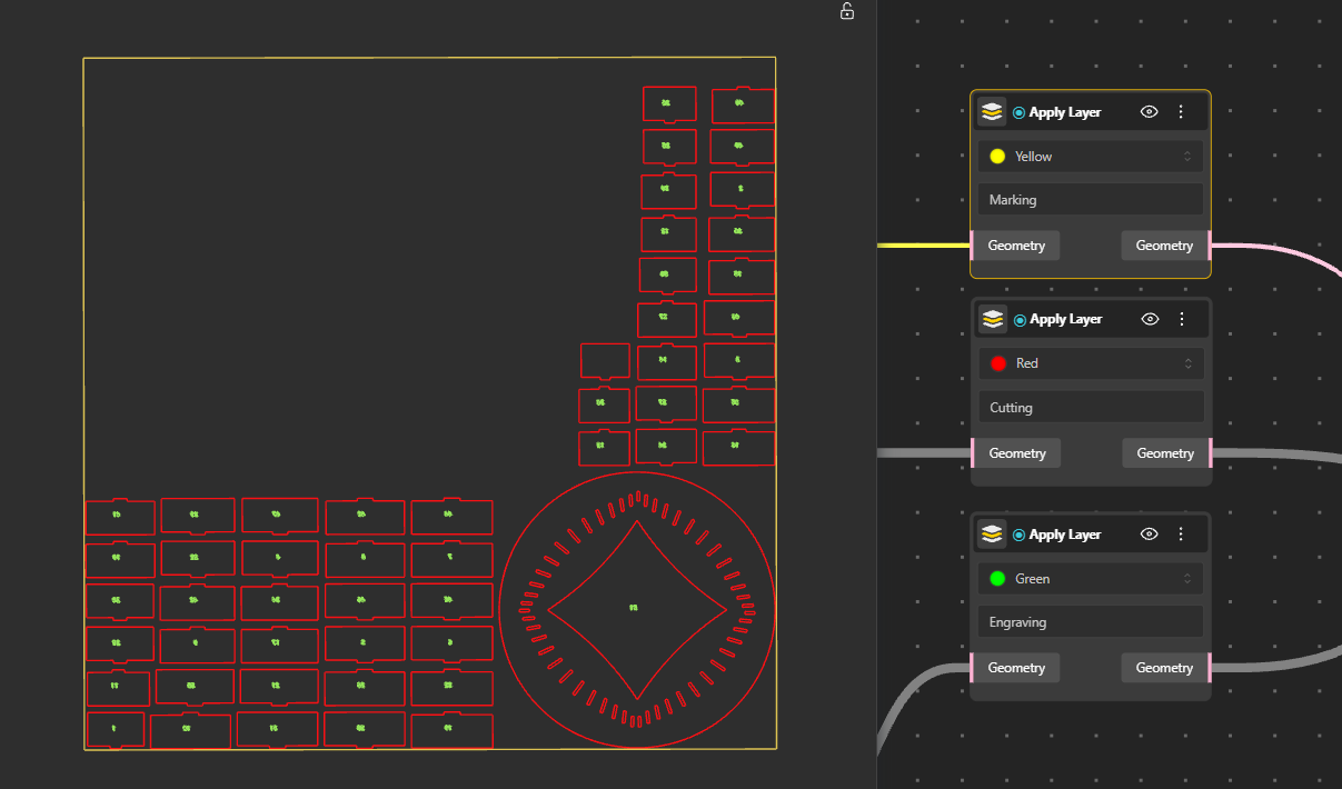
Apply Material turns the bare layout into something a machine can act on. It assigns a real material to your parts, so the layout carries actual values like thickness and sheet size, and it color-codes every line by the operation the machine should perform:
Red for cutting
Yellow for marking
Blue for internal cutting
Green for engraving
Magenta for hatching and filled areas
Cyan for dimensions and annotations
Machine connects the prepared layout to your fabrication setup, and G-code generates the instructions that actually drive the cut.
A part came back with Sheet ID -1. It did not fit on the available sheets. Increase the sheet size, allow the job to use more sheets, enable rotation if the node supports it, or try a packer that places parts more tightly.
The nest is slow. True-shape and genetic nodes do the most work. Lower Num Cursors, reduce Rotation Steps, loosen Curve Tolerance, or switch to a simpler packer for previews.
Parts overlap or the layout looks wrong. Make sure every part is flattened to a single plane, and set Spacing to account for your kerf.
The result changes every time I run it. The node is using randomness. Set a fixed Seed to lock the layout in place.
The nested layout overlaps my source geometry. Change the Origin to move the result somewhere clear.