Machines in BeeGraphy are part of the CAM (Computer-Aided Manufacturing) workflow. While CAD helps you design models, Machines enable you to fabricate those designs in the real world by generating machine-ready instructions (G-code).
Machines are primarily used by businesses integrating configurators into their websites, allowing them to:
Receive customer orders
Generate manufacturing files
Run production directly on their machines
Machines are essential for bridging the gap between design → production.
Business Dashboard
View incoming orders and quotes
Download machine-ready files (G-code)
Execute production using assigned machines
Configurator Integration
Machines are linked to parametric models
When a user configures a product, the system:
Assigns a machine
Generates toolpaths
Outputs G-code specific to that machine
Each machine defines how a design is manufactured.
A machine profile typically includes:
Working Area (size limits)
Spindle Speed (RPM)
Feed Rate (movement speed)
Post-Processor (translates toolpaths into machine-specific G-code)
Z0 Position (reference point for cutting)
These parameters ensure that the generated G-code matches the physical capabilities of the machine
Important Note: Currently, machines are not added directly by regular users.
They are:
Created by administrators
Provided to business clients
Selected from a predefined list
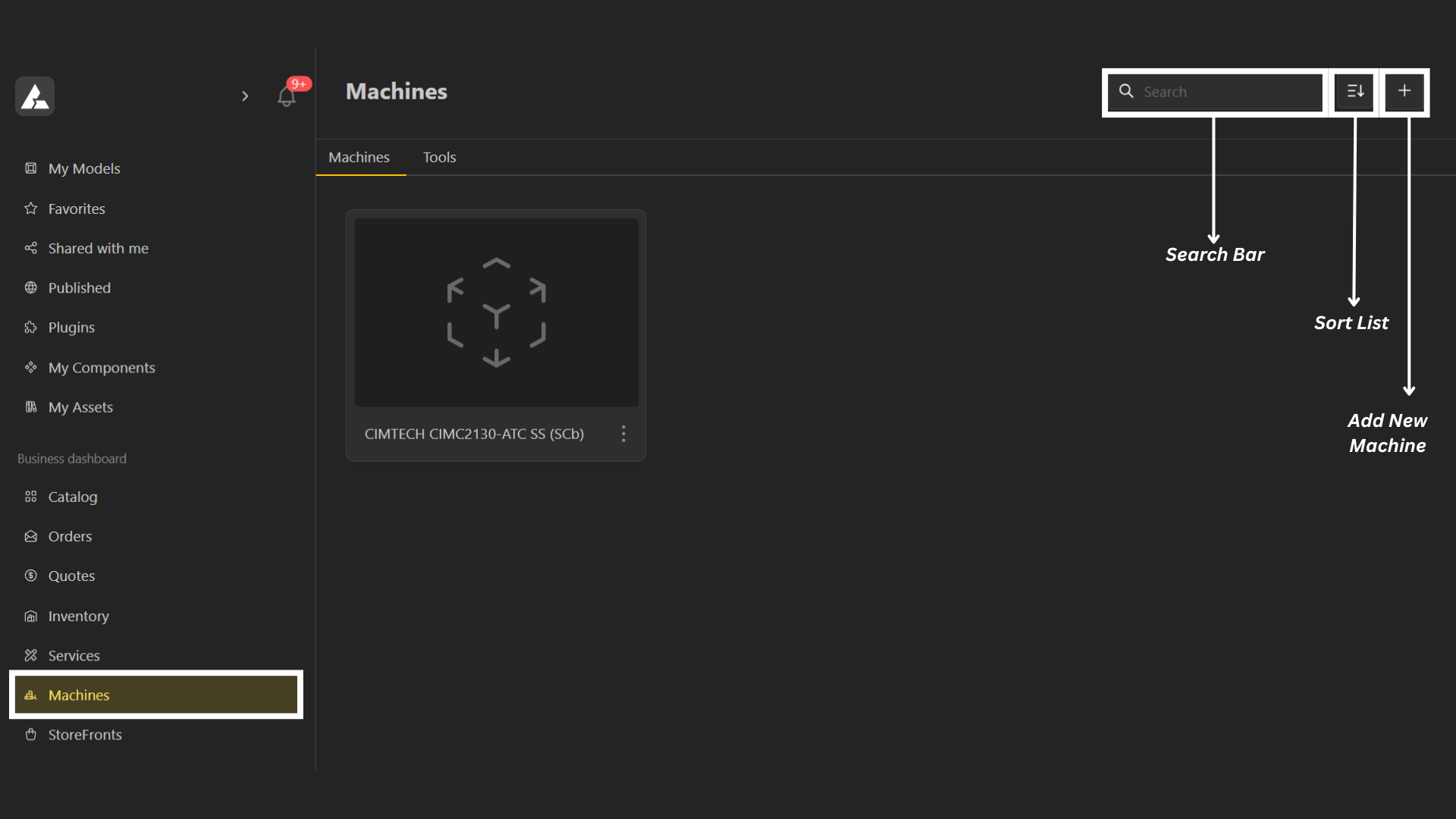
Click on the Add Icon on top right corner to create a new Machine Profile.
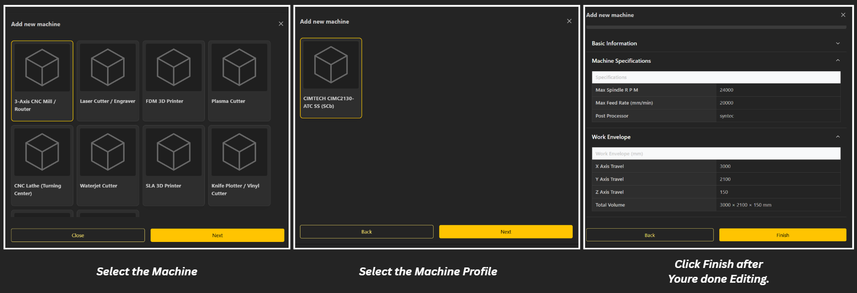
Select the Machine you want to Add.
Choose the Machine Profile.
Define machine parameters:
Working area
Spindle capacity (RPM)
Feed rates (X/Y movement)
Z-axis setup
Post-processor
Save the machine
Once created:
The machine becomes available in the selection list
Businesses can assign it to their workflows
To generate manufacturing output:
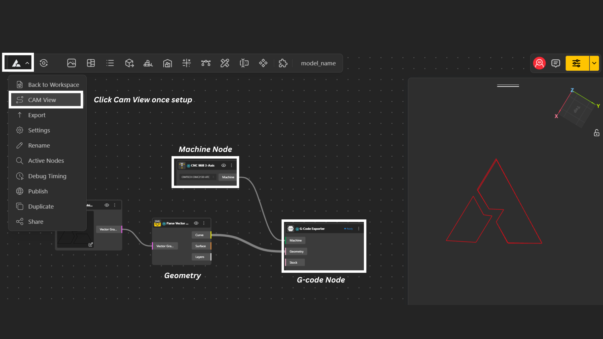
Open your model
Add the G-Code Exporter to your Model.
Assign:
Machine
Geometry
Select the Machine.
Click on the Main Menu to drop down menu.
Select CAM view.
The machine determines:
Movement instructions
Tool behavior
Output format
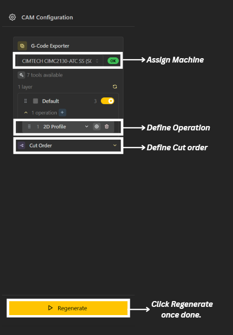
Assign Machine: Select the appropriate machine for your model. The machine defines:
Working limits
Feed rates & spindle behavior
Post-processor (G-code format)
The same design can generate different outputs depending on the selected machine.
Define Operations: Set up the machining operations required for your model, such as:
2D Profile (cutting contours)
Pocketing (removing internal material)
Engraving / marking
Each operation determines how the tool interacts with the geometry.
Define Cut Order: Arrange the sequence of operations carefully. Typical order:
Engraving / marking
Internal cuts (holes, pockets)
External profile cuts
Proper sequencing prevents part movement and ensures machining stability.
Assign Tool Number: Select the correct tool for each operation.
Diameter (affects offset and accuracy)
Feed & speed limits
Cutting capability
Tool numbers correspond to real machine tools (e.g., tool changer slots).
Configure Cutting Parameters: Before generating, ensure:
Cut depth
Step-down (depth per pass)
Safe Z & retract height
Lead-in / lead-out settings
Tabs (to hold parts in place)
Dog bones (for internal corners, if needed)
These settings directly affect both safety and output quality.
Click Generate / Regenerate: This step
Creates toolpaths
Applies offsets based on tool diameter
Converts paths into machine instructions (G-code)
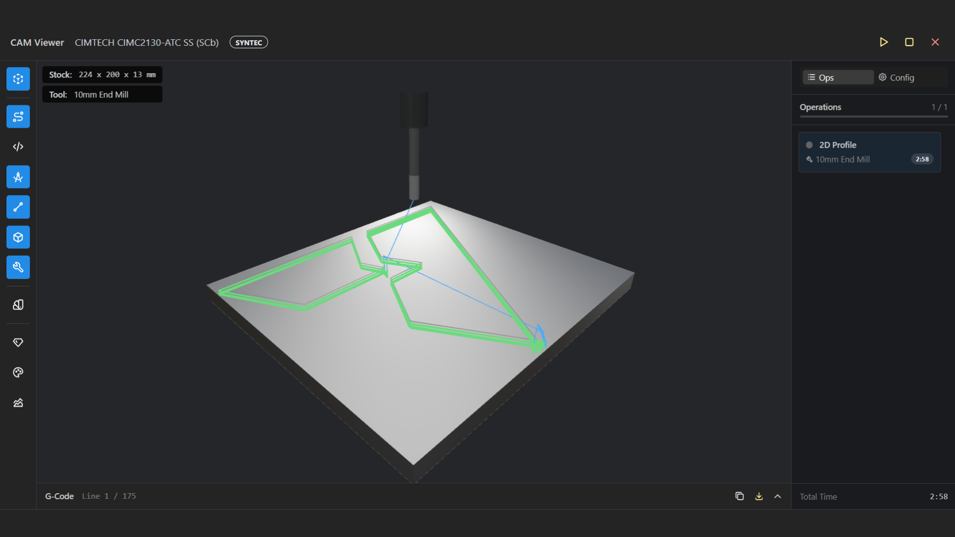
Visualize Simulation: Your generated simulation is now ready. You can now
Preview tool movement
Verify cut order
Check rapid vs cutting moves
Identify potential issues (collisions, wrong depths, missing cuts)
Note: Simulation is still evolving and may not reflect exact real-world timing or behavior.
When a customer places an order:
The configurator generates a custom design
The system:
Applies machine settings
Generates G-code
The business dashboard shows:
Order details
Downloadable manufacturing file
Manufacturer runs the file on their machine
This enables one-click manufacturing workflows once setup is complete.
Machine Nodes
Get to know about Machine Nodes