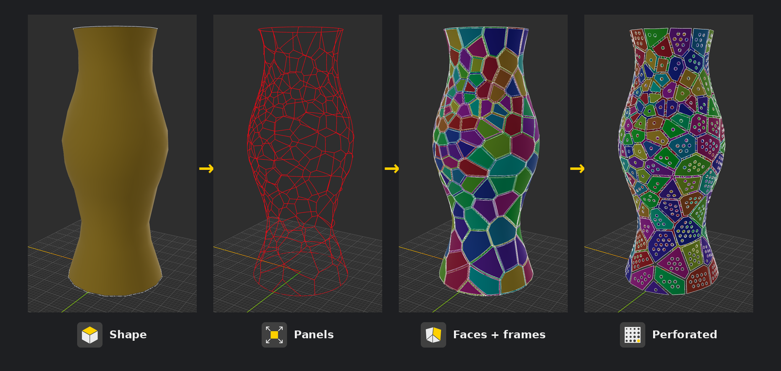
Panelization breaks a surface, solid or mesh into panels you can actually make. This article covers how to add the plugin, build a panelized model step by step, check the panels for fabrication, and take them through scheduling, nesting and labeling to cut sheets.
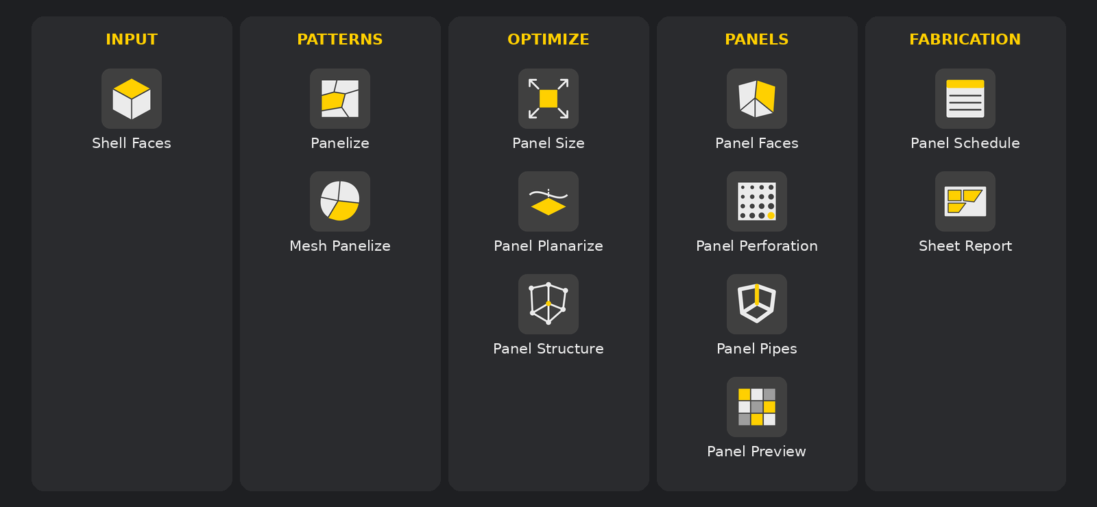
The plugin takes your design geometry all the way from a raw shape to labeled parts on a sheet. Its 12 nodes are organized into five groups:
Input: Shell Faces splits a solid into its faces so every later node works face by face.
Patterns: Panelize turns a surface into trimmed panels (Voronoi, UV Grid, Triangulation or Hexagonal). Mesh Panelize does the same for meshes such as scans.
Optimize: Panel Size keeps panels between a minimum and maximum size, Panel Planarize flattens and measures panels, and Panel Structure checks the frame members and joints.
Panels: Panel Faces builds the panel faces and frames, Panel Perforation adds holes, Panel Pipes previews a tube frame and Panel Preview colors the panels for checking.
Fabrication: Panel Schedule groups panels into part types and lays them out flat, and Sheet Report reads the nesting result to place labels and report sheets, yield and cutting problems.
The node icons, grouped as they appear in the BeeGraphy node menu:
Optional steps that add material or patterning (gap, frame, perforation, pipes, planarize, structure, attractors) are off by default, so a minimal graph stays simple.
Use one set of units. Panel sizes, frame widths and hole sizes are in model units. When you nest the panels later, the sheet size must be in the same units, or the yield will look wrong.
Start small. Panel Faces and Panel Perforation build real geometry for every panel and are the slowest nodes. Test your settings with a lower panel count, then raise it for the final model.
Keep previews to what you need. Turn off the preview (eye icon) on nodes you are not looking at, so the viewer stays fast.
Find Panelization and select + Add to add it to your workspace editor.
Open or refresh the workspace editor and find the Panelization group in the toolbar menu.
From the node menu, drag the node you want onto the canvas.
The typical graph runs Shell Faces → Panelize → Panel Size → Panel Faces → Panel Schedule → nesting → Sheet Report. The checking nodes (Panel Preview, Panel Planarize, Panel Structure, Panel Pipes) branch off along the way. Most nodes need both the panel curves and the Surface from Panelize, so wire that Surface output to every later node that has a Surface input.
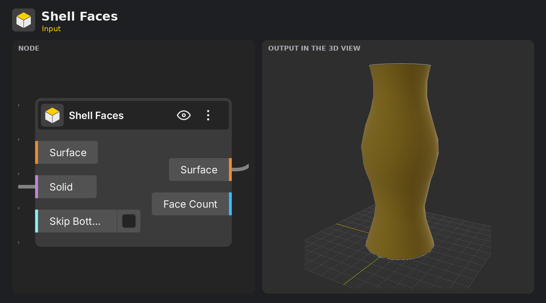
Connect a solid, a multi-face surface or a list of surfaces to Solid. With nothing in Solid, the single Surface input passes straight through.
Turn on Skip Bottom to leave out the flat bottom face, for example on a vase or a building standing on the ground.
The Surface output gives one face per item, and Face Count tells you how many there are. Because panels are made face by face, they end exactly on the face edges.
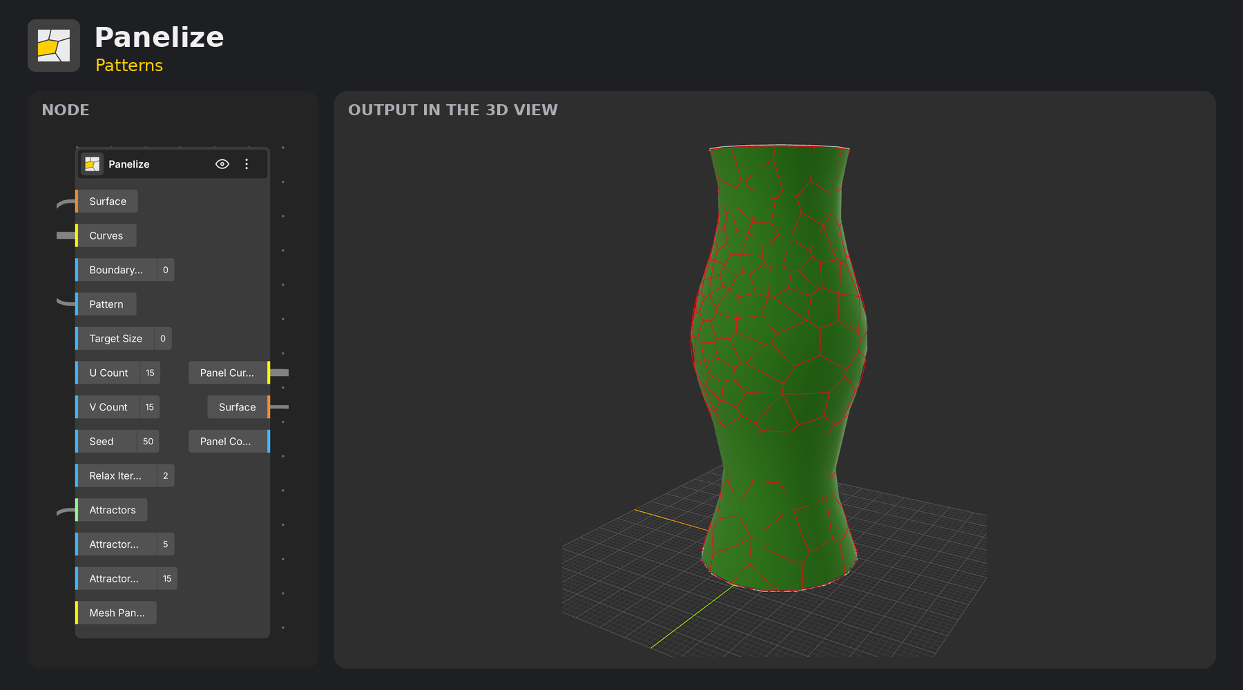
Panelize is the core node. Connect the Shell Faces Surface to its Surface input, then set:
Pattern: 0 Voronoi, 1 UV Grid, 2 Triangulation, 3 Hexagonal, 4 Mesh (panels coming from Mesh Panelize).
Target Size: the panel span in model units and the main density control. Corners near the outline snap onto it automatically. Leave it at 0 to use U Count and V Count instead.
U Count / V Count: columns and rows when Target Size is 0.
Seed and Relax Iterations: change the random layout and make cells more even (Voronoi and Triangulation).
Attractors, Attractor Strength and Attractor Radius: points that make panels smaller near them. Strength 0 switches this off. The points should sit on or near the surface to have an effect.
Boundary Mode with Curves: 1 builds the surface from boundary curves, 2 trims the surface to them. At 0 the Curves input is ignored.
Outputs: Panel Curves (one closed outline per panel, on the surface), Surface (wire it to every later node) and Panel Count.
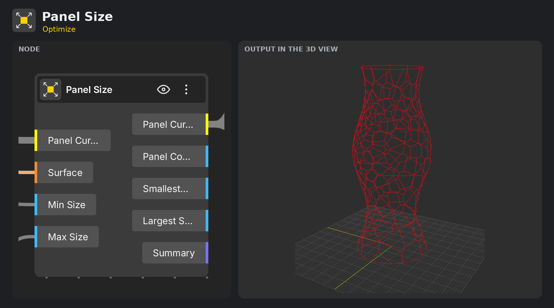
Panel Size keeps every panel between Min Size and Max Size (measured as the panel span). Panels that are too big are split. Panels that are too small grow by pushing their shared corners outward along the surface, but only into neighbors that are themselves above Min Size, so panels are never merged. Set either value to 0 to switch it off.
Read the Summary output: it lists the panel count, splits and the span range, and warns when panels are still outside your limits. If the whole pattern is too fine, it is left unchanged with a warning; raise Target Size or lower U / V Count in Panelize instead.
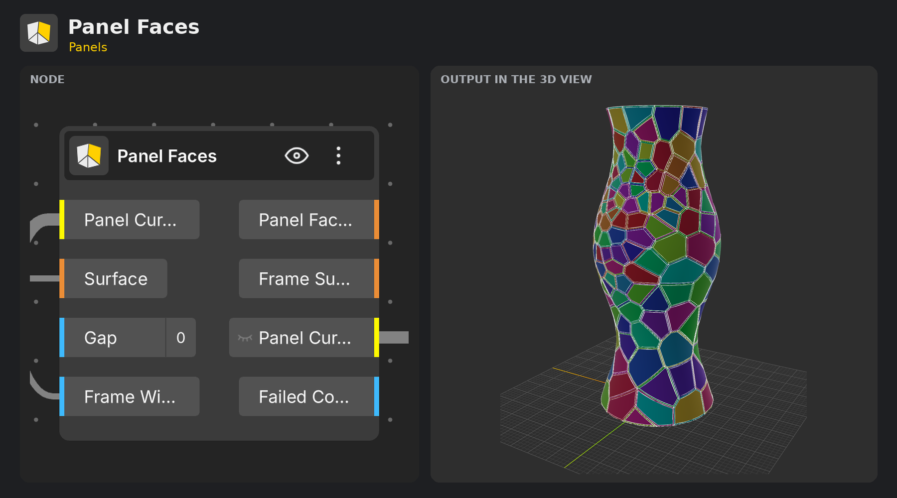
Gap: the joint width between neighboring panels. Panels shrink so neighbors sit this far apart. 0 = off.
Frame Width: a mitered border band inside every panel. A panel too narrow for the frame becomes one solid frame piece. 0 = off.
Flat panels are filled directly. Curved panels are cut from the surface so neighbors meet without gaps.
Outputs: Panel Faces, Frame Surfaces (one frame per panel), Panel Curves (the final outlines after gap and frame, used by Panel Preview and Panel Perforation) and Failed Count (panels too small for the gap or frame, or that could not be built).
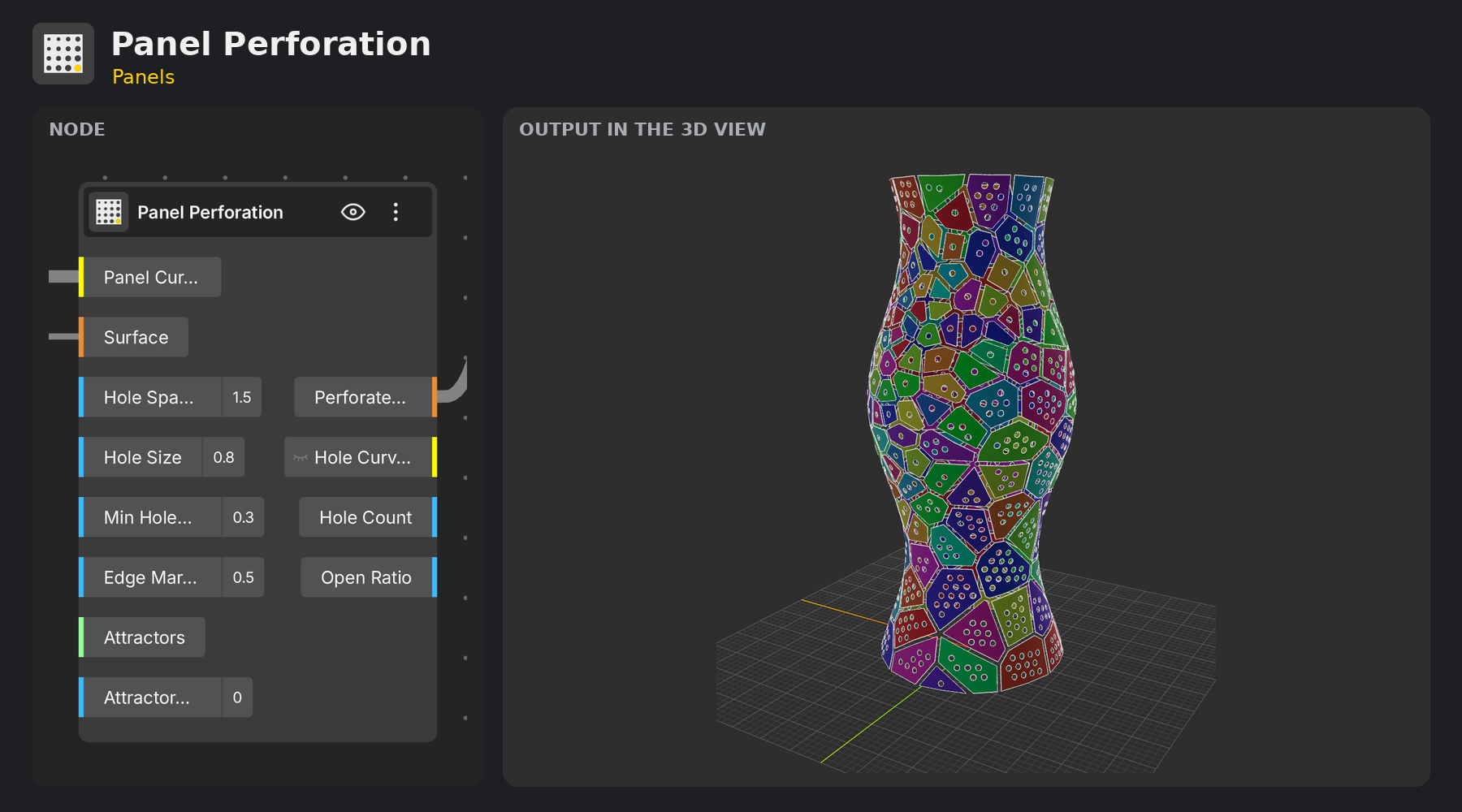
Connect the Panel Curves output of Panel Faces and the Surface from Panelize. Set Hole Size above 0 to switch perforation on, then tune Hole Spacing, Min Hole Size and Edge Margin (the distance kept from the panel edge). Add Attractors to grade the holes toward points, with Attractor Radius controlling the reach (0 = automatic).
Outputs: Perforated Panels, Hole Curves, Hole Count and Open Ratio (the share of the panel area that is open).
These nodes report on the panels without changing your main chain, so you can add them anywhere after Panel Size.
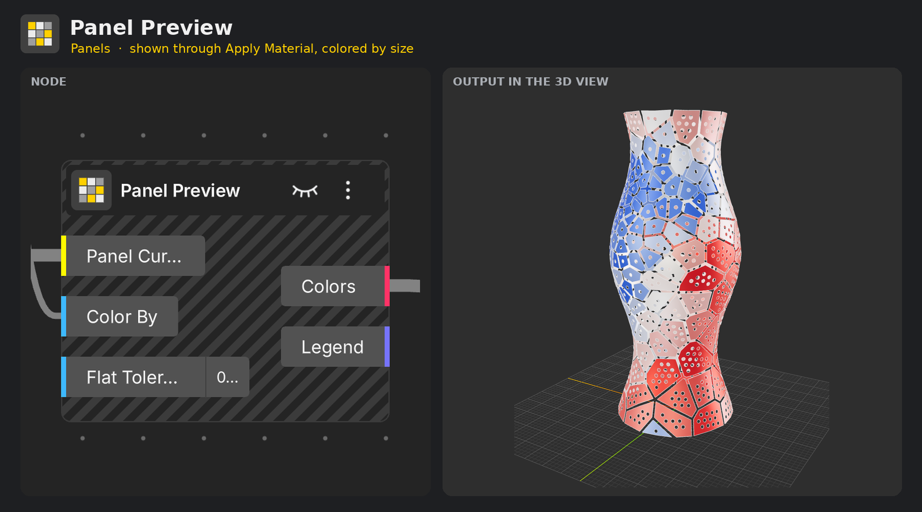
Panel Preview gives one color per panel for Apply Material. Set Color By to 0 Panels, 1 Flatness, 2 Size or 3 Type, and read the Legend output to see what the colors mean.
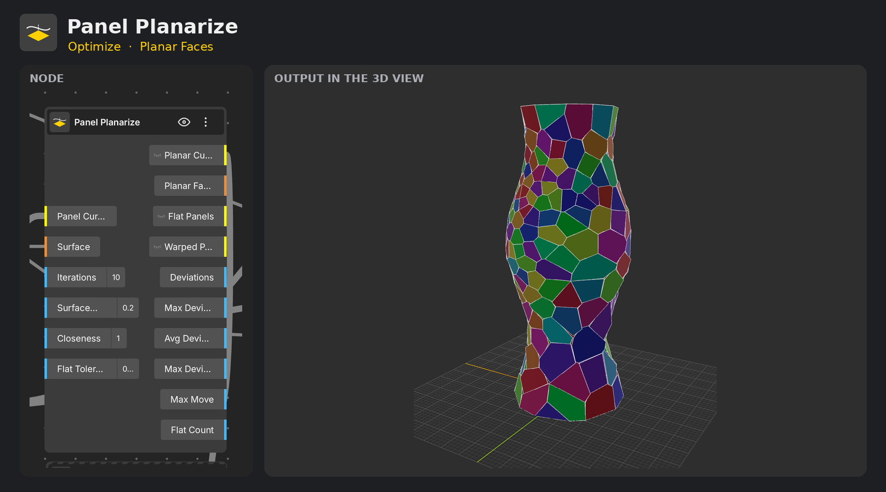
Panel Planarize moves panel corners so every panel becomes flat while neighbors keep sharing corners. Iterations sets how many rounds of corner moving run (0 only measures), Surface Weight keeps corners on the surface (1) or lets them move freely (0), Closeness pulls them back to their original position, and Flat Tolerance sets the deviation that counts as flat. Planar Faces are always exactly flat, ready to cut, and Flat Panels, Warped Panels and Max Deviation show how far you are from a flat-panel design.
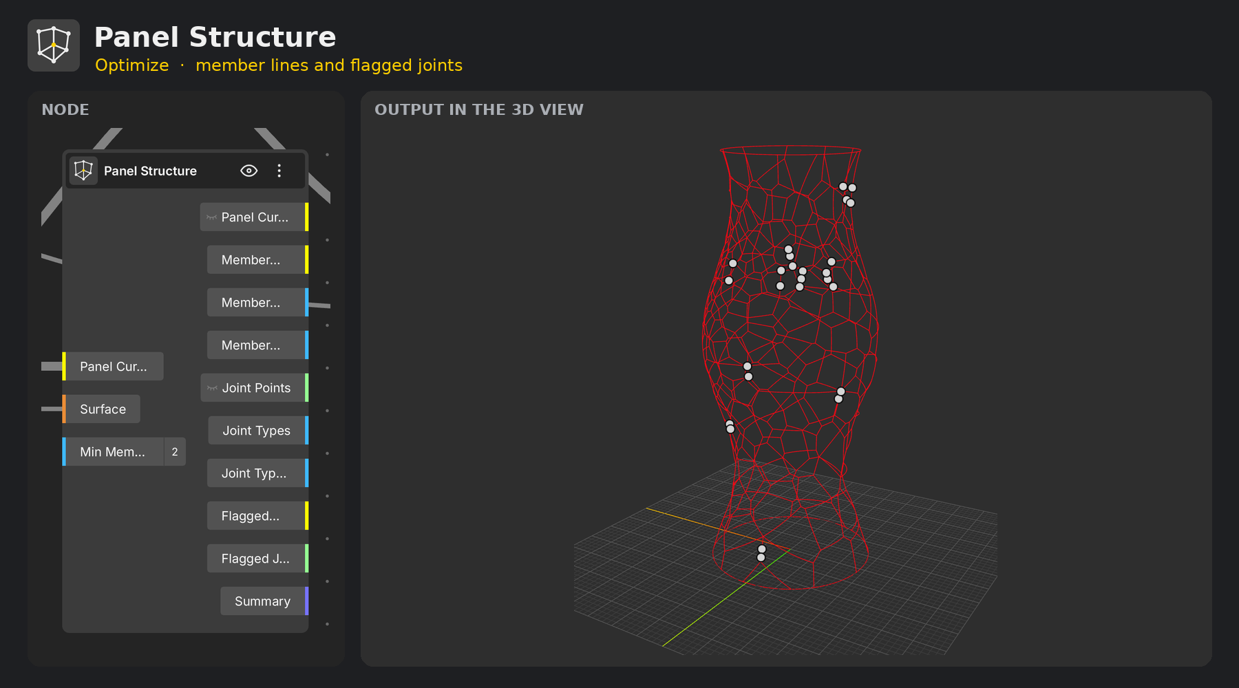
Panel Structure finds one frame member per shared panel edge and the joints where they meet. Set Min Member Length to flag members that are too short to make, and read the member and joint types to see how many different lengths and angles you need.
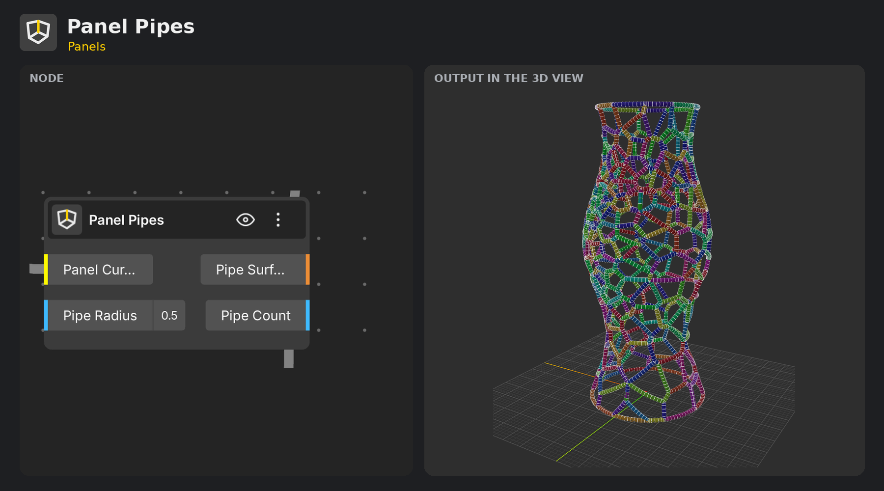
Panel Pipes previews a frame as tubes along shared edges with a ball at every corner. Set Pipe Radius above 0 to switch it on.
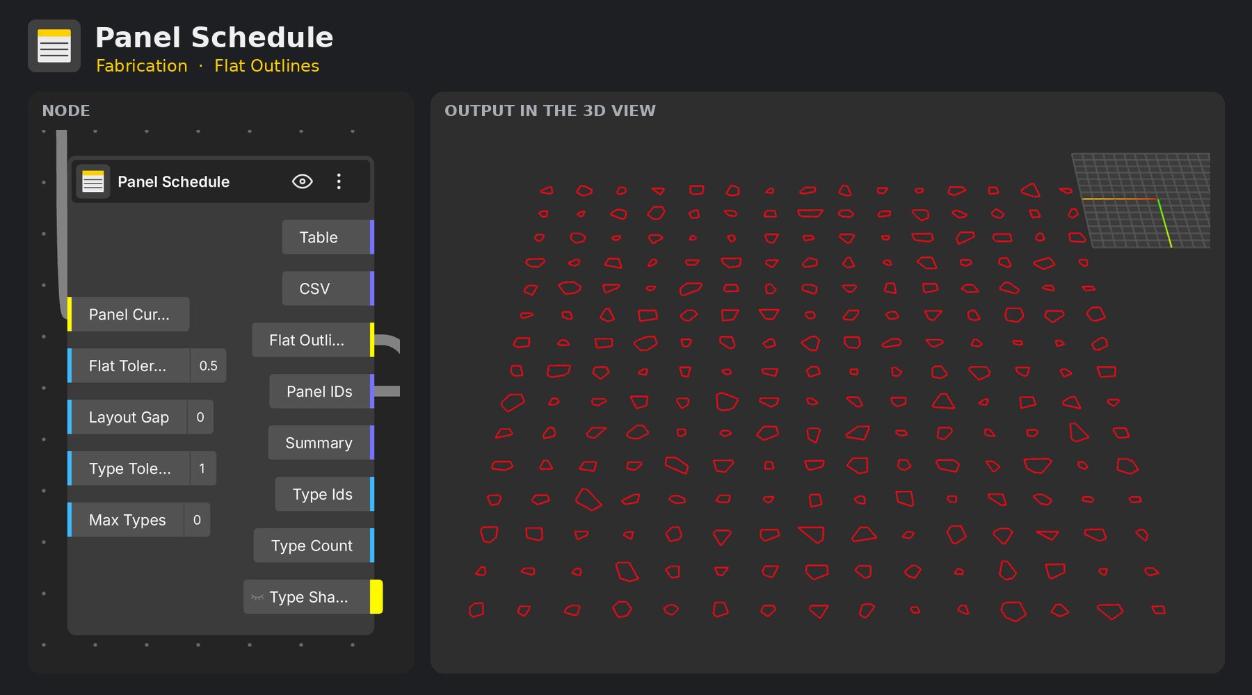
Panel Schedule groups panels with the same flat shape (mirror images included) into part types and gives one row per panel: ID, part type, corners, area, perimeter, deviation, status, centroid and unroll error. It also unrolls every panel flat for cutting.
Type Tolerance sets how close two shapes must be to share a part type (0 = no part types). Max Types raises the tolerance until there are at most that many types.
Flat Tolerance sets the deviation that counts as flat, and Layout Gap sets the spacing of the laid-out flat panels.
Wire Flat Outlines to your nesting node and Panel IDs (labels such as 5-3, meaning panel P05, type T3) to Sheet Report. Table feeds a Display Table, and CSV can be exported.
Connect Flat Outlines to a nesting node such as Nesting Polygon Genetic and set the sheet size and spacing. See the Nesting in BeeGraphy article for how to choose a nesting node and set it up. Make sure the sheet size uses the same units as your model.
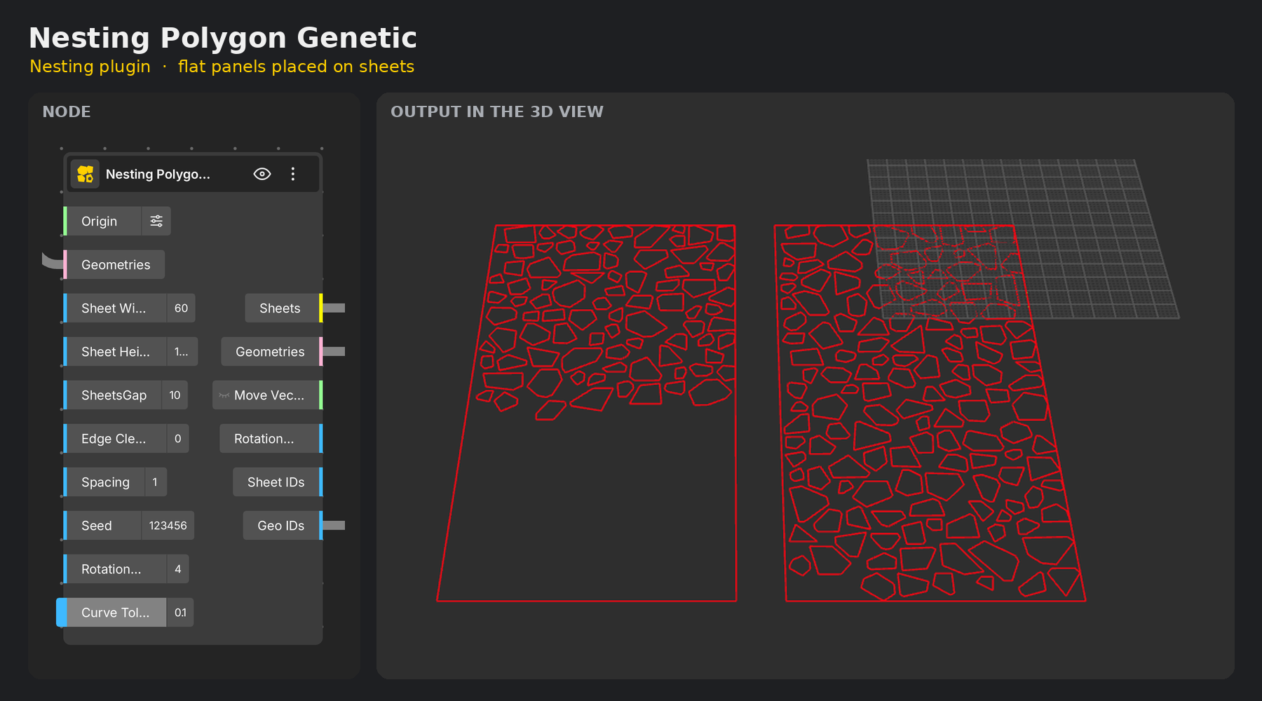
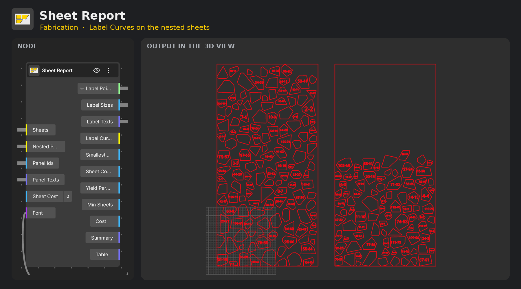
Connect the nesting outputs to Sheet Report: Sheets to Sheets, Geometries to Nested Panels and Geo IDs to Panel Ids. Connect Panel Schedule Panel IDs to Panel Texts, and optionally enter a Sheet Cost.
Connect a Font node to the Font input to get Label Curves: the engraving text for every part, centered in the part and checked to stay inside its outline with a margin. Without a Font, Sheet Report still gives Label Points, Label Sizes and Label Texts for a Text node.
Sheet Report also returns Sheet Count, Yield Percent, Min Sheets (the fewest sheets possible), Cost and a Summary with a cutting check that warns about overlapping parts or parts over the sheet edge.
For scans or imported models, use Mesh Panelize on the mesh. Set Panel Count or Target Size and a Seed, then connect its Panel Curves to the Mesh Panels input of Panelize with Pattern set to 4. From there the workflow is the same: Panel Planarize, Panel Faces, Panel Schedule and Sheet Report.
Node | What it does | Key inputs | Key outputs |
|---|---|---|---|
Shell Faces | Splits a solid into faces | Solid, Surface, Skip Bottom | Surface, Face Count |
Panelize | Turns a surface into panels | Pattern, Target Size, U / V Count, Seed, Attractors | Panel Curves, Surface, Panel Count |
Mesh Panelize | Panels on a mesh | Mesh, Panel Count, Target Size, Seed | Panel Curves |
Panel Size | Keeps panels within a size range | Min Size, Max Size | Panel Curves, Smallest / Largest Span, Summary |
Panel Planarize | Flattens and measures panels | Iterations, Surface Weight, Closeness, Flat Tolerance | Planar Curves, Planar Faces, Flat / Warped Panels, Max Deviation |
Panel Structure | Checks frame members and joints | Min Member Length | Member Lines, Member / Joint Types, Flagged Members, Summary |
Panel Faces | Builds faces and frames | Gap, Frame Width | Panel Faces, Frame Surfaces, Panel Curves, Failed Count |
Panel Perforation | Adds round holes | Hole Size, Hole Spacing, Min Hole Size, Edge Margin, Attractors | Perforated Panels, Hole Curves, Hole Count, Open Ratio |
Panel Pipes | Previews a tube frame | Pipe Radius | Pipe Surfaces, Pipe Count |
Panel Preview | Colors panels for checking | Color By, Flat Tolerance | Colors, Legend |
Panel Schedule | Part types and cutting list | Type Tolerance, Max Types, Flat Tolerance, Layout Gap | Table, CSV, Flat Outlines, Panel IDs, Type Count |
Sheet Report | Labels, yield and cutting check | Sheets, Nested Panels, Panel Ids, Panel Texts, Font, Sheet Cost | Label Curves, Sheet Count, Yield Percent, Min Sheets, Cost, Summary |
Panel Size warns that panels are below Min Size. The pattern is too fine to grow without shrinking neighbors. Raise Target Size or lower U / V Count in Panelize, or lower Min Size.
Every panel counts as flat. Flat Tolerance is too high, so even warped panels pass. Lower it (for example to 0.05), and remember that with Iterations at 0 Panel Planarize only measures and does not flatten.
Failed Count is above 0 in Panel Faces. Some panels are too small for the Gap or Frame Width. Lower those values or make the panels bigger.
Labels do not appear. Connect a Font node to the Font input of Sheet Report to get Label Curves.
The yield is very low. The sheet size and the model are probably in different units. Use the same units for both.
Attractors have no effect. Move the points onto or near the surface, and make sure Attractor Strength is above 0.
Boundary curves are ignored. Set Boundary Mode to 1 or 2 in Panelize.
A node still shows old inputs after a plugin update. Delete the node and add it again from the node menu to get the latest inputs and outputs.
The graph is slow. Panel Faces and Panel Perforation do the most work. Test with fewer panels and turn off previews you do not need.