3D output window lets you view your model in a fully interactive 3D space. You can orbit, pan, and zoom to inspect every part of your geometry, understand how your parameters affect the shape, and verify the final output visually. It’s the best mode for reviewing your model’s form, spotting issues, and presenting your work clearly.
The 3D Output Window is the output window in your Editor, used to see the real-time results of your model as you build and adjust it.
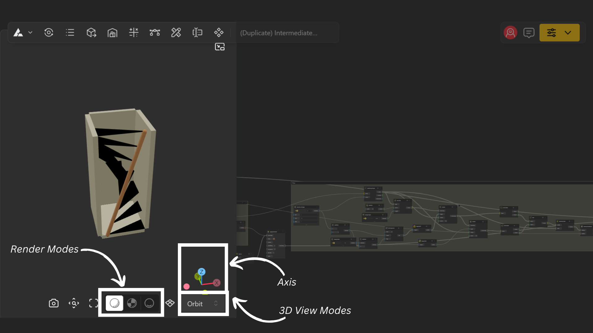
There are four (default) types of Views as followed:
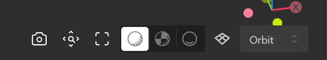
Orbit: Freely rotate around your model to see it from any angle.
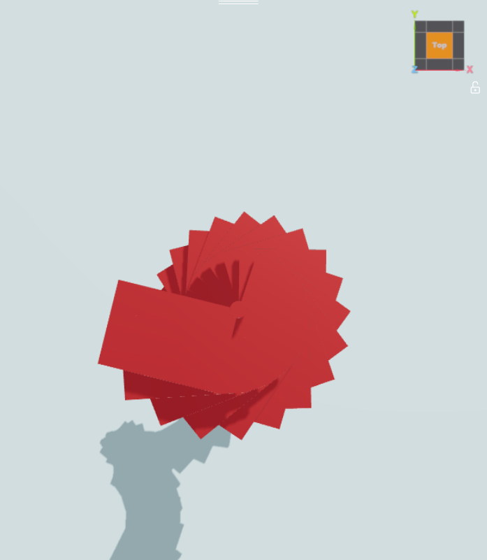
Top: Shows your model from directly above.
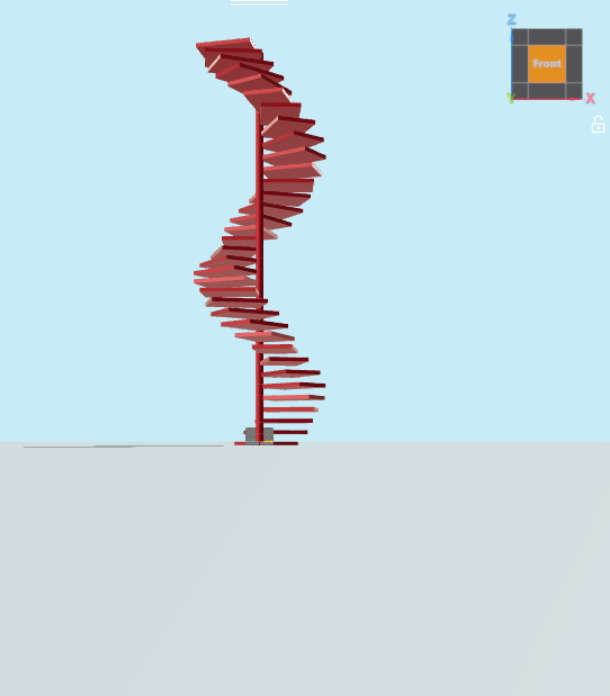
Front: Displays the model from the front-facing direction.
Right: Shows the model from the right-side view.
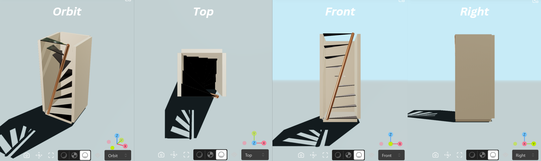
And it offers three Rendered Modes:
Shaded: Displays your model with basic colors and surfaces for easy visualizing.
Render: Shows a more realistic view with lighting, reflections, and materials.
Shadow: Displays your model with shadows enabled to better understand depth and form.
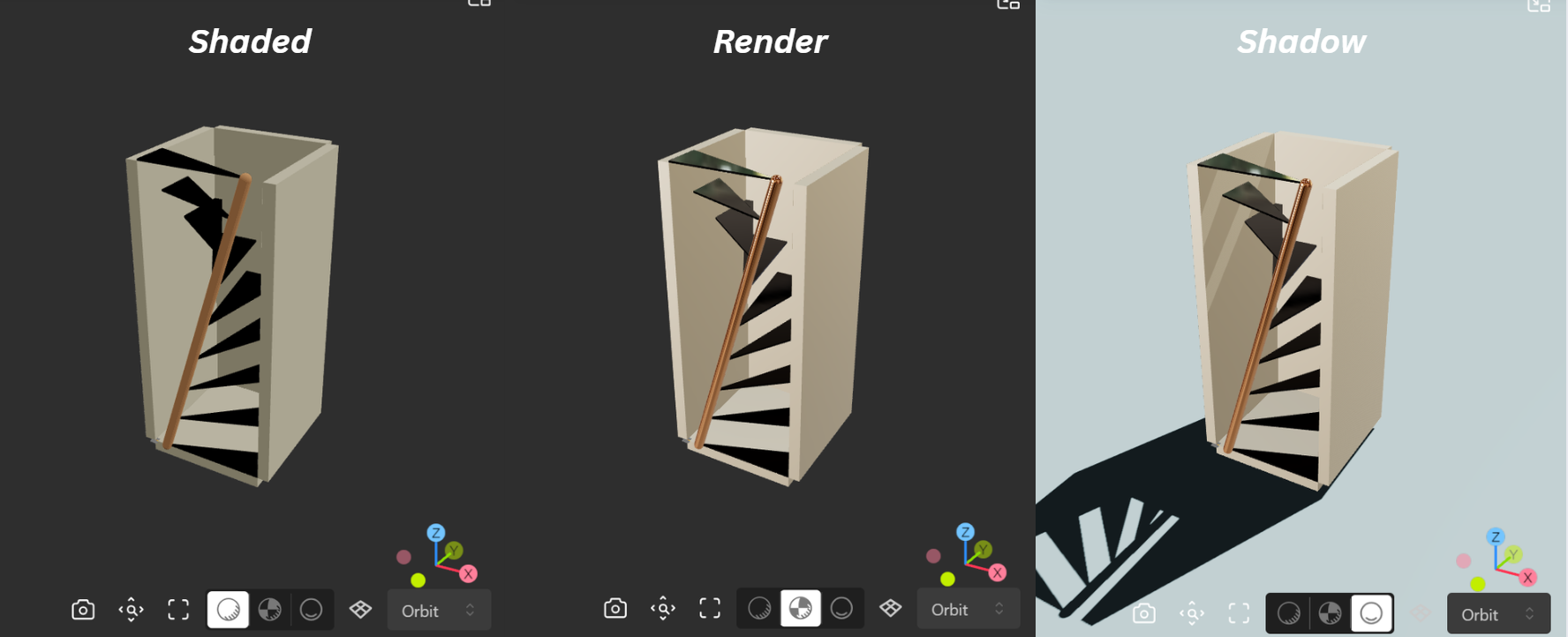
To adjust the 3D view, simply select the desired mode from the bottom menu.
BeeGraphy introduces Gizmo that enhances spatial orientation, navigation clarity, and overall viewport control within the Editor.
Placed at top-right corner for better visibility and alignment with common 3D workflows, the gizmo includes clear axis labels, face-based view indicators, and interactive view switching for quick access to orthographic views.
A dedicated Viewport Lock further helps prevent accidental view changes, keeping the workspace clean, precise, and intuitive during modeling and inspection.
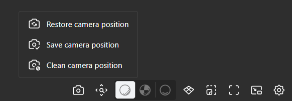
The Camera Ports give you better control over how models are viewed in the 3D viewport and how they appear when published.
The Save Camera Position port allows you to store the current camera view. When a model is published, the saved camera position becomes the default view for anyone opening the model. This ensures that viewers see the model from the intended angle and framing chosen by the creator. This is especially useful when presenting models or product configurations where a specific viewing angle is important.
The Restore Camera Position port returns the viewport camera to the previously saved position. This allows you to quickly return to a defined camera view while working on a model.
The Clear Camera Position port removes any saved camera view. Once cleared, the model will no longer have a fixed camera position and will instead open using the default viewer controls.
The 3D Viewer settings allow you to control how your model is visually represented in the viewport. These options are designed to help you inspect geometry, debug models, and customize your viewing experience.
Grid: Shows a reference grid (XY Plane)
Axes: Displays X, Y axes for orientation
Wireframe: Reveals the mesh structure and topology
Transparent: Makes the model see-through to inspect internal parts
Normals: Visualizes surface directions.
Edges: Highlights sharp and feature edges for clarity
Level of Detail (LOD) is a performance technique where the 3D engine automatically renders geometry at different levels of complexity depending on how close or far the camera is. The idea is simple, if you're zoomed far out, there's no need to render every fine detail, so the engine uses a simplified version to save processing power. There are 4 option for Quality: Low, Medium, High and Custom.
You can enable multiple view types at once for deeper inspection. These settings only affect visualization and do not impact the final output.
Interactive Geometry Selection allows you to directly interact with geometry in the 3D viewport to identify which node produced it. Instead of manually searching through a large and complex graph, the viewport itself becomes an intuitive way to navigate and analyze your parametric workflow.
Navigate to the 3D viewport where your model is displayed.
Click on any part of the geometry you want to inspect.
If a single node is responsible for that geometry, it will be selected automatically in the node graph.
If multiple node outputs overlap at that point, a dropdown menu will appear showing all related nodes.
Select a node from the dropdown, and you will be taken directly to that node in your graph.
Measurement Support lets you measure your model directly in the 3D viewport, so you can check real dimensions and distances as you inspect your geometry, without leaving the output window or going back to the node graph.
You can now measure length, angle, and area directly within the 3D viewport, without leaving the output window. Measurement labels automatically face the camera, so they stay clear and readable from any angle. Like the other viewer tools, measurements are for inspection only and do not affect the final output.
With measurement active, you can pick points on your model and read the distance between them right in the view. This makes it easy to verify a part's size, check the gap between two features, and confirm your parameters produced the geometry you expected before you move on to fabrication.
To measure:
Open the 3D view in the output window.
Activate the measurement tool.
Click the points or elements you want to measure between, and the distance is shown in the view.
Capture View lets you save specific camera positions directly within a model, making it easier to guide reviews, presentations, and walkthroughs. Moving between saved views uses smooth camera transitions, and control returns to you the moment you start navigating manually.