Here are some of the core commonly used tools in BeeGraphy that are particularly useful for beginners to familiarize themselves with. They provide a strong foundation for creating geometry, applying transformations, organizing data, and streamlining the overall design workflow.
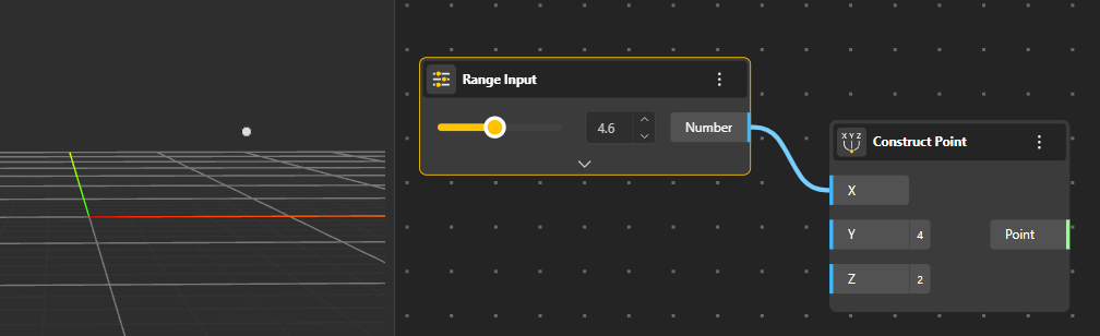
Create points manually or from coordinates. You can also use a range input. Range Input help define an adjustable interval within which you can move a slider to generate points dynamically. This allows you to explore different point positions interactively by selecting values anywhere within the specified range.
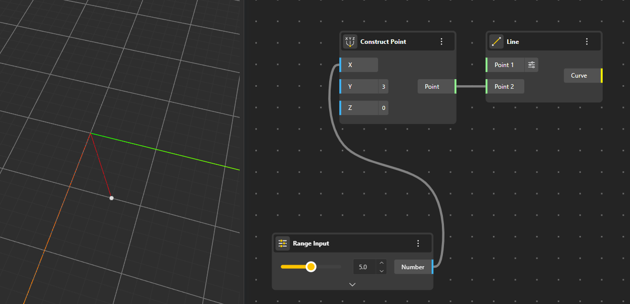
Creates straight lines defined by two points. You can also generate a line using the Line SDL method, which constructs a line from a starting point and a direction vector. This approach allows you to specify and control the exact length of the resulting line.
You can manually input the coordinates or connect a Construct Point node to define the endpoints. Using a Range input also allows you to create an interactive line whose position updates dynamically as you adjust the slider.
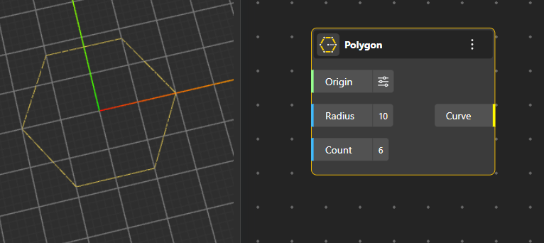
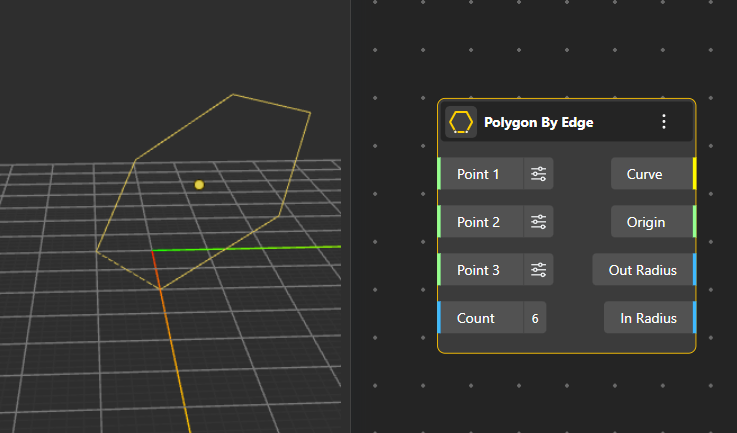
Creates closed shapes such as regular polygons. One method is to define the center, radius, and number of sides to generate the polygon directly. Another option is to specify three points along with a radius, allowing the polygon to be constructed based on positional references.
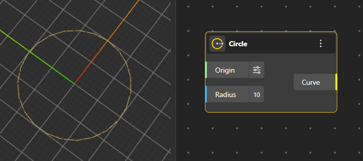
Generates circular geometry using four different construction methods:
Circle: The simplest approach—define the origin and the radius to create a standard circle.
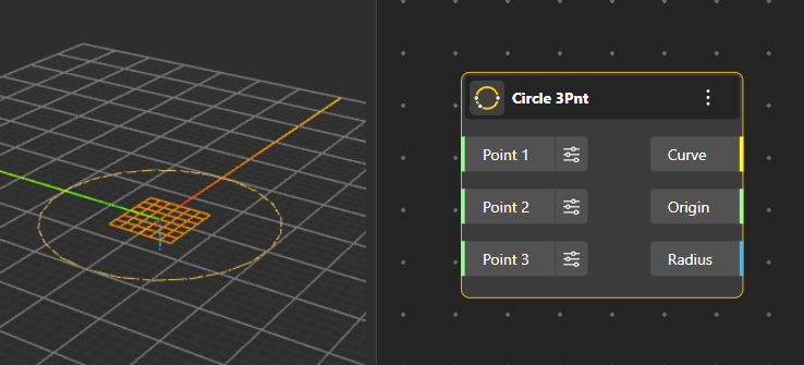
Circle 3pnt: Constructs a circle that passes through three specified points, ensuring the geometry fits those exact positions.
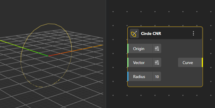
Circle CNR: Creates a circle oriented in a specific direction by defining a point, a normal vector, and a radius instead of relying on multiple points.
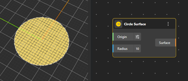
Circle Surface: Produces a 2D filled surface of a circle using a defined origin and radius, useful for surface-based operations.
Creates rectangular geometry using multiple construction methods:
Rectangle: Defines the rectangle using a starting corner point, along with specified length and width values.
Rectangle by Center: Constructs the rectangle by selecting a central point and defining its length and width, allowing the shape to expand evenly around the center.
Rectangle 3-Point: Generates a rectangle using three points, where the first two determine one edge and the third sets the orientation and width.
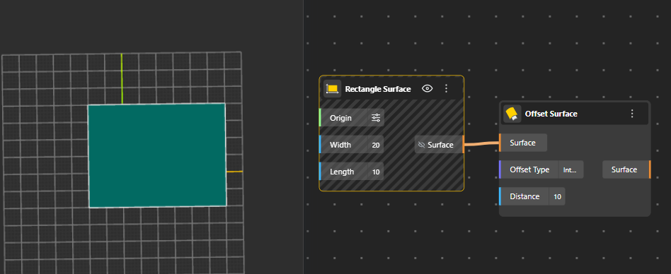
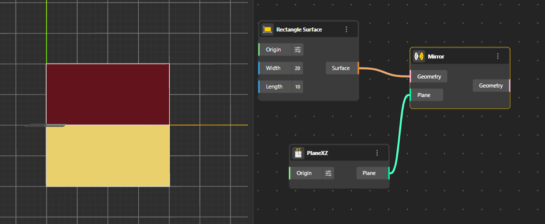
Rectangle Surface: Produces a filled 2D surface version of the rectangle, same as the rectangle curve node.
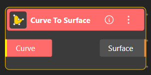
Converts any curve into a Surface.
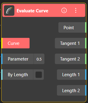
The Evaluate Curve node allows you to extract detailed geometric information from any point along a curve. You can evaluate the curve either by its parameter value (typically between 0 and 1) or by a specific curve length.
Inputs:
Curve: The curve you want to evaluate.
Parameter: A value (usually 0–1) that represents a position along the curve. For example, 0.5 returns the midpoint.
By Length (toggle): When enabled, the node interprets the input as a length value instead of a parameter.
If ON → the number you enter corresponds to length along the curve.
If OFF → the number corresponds to a parameter value.
Outputs:
Point: The exact point on the curve at the selected parameter or length.
Tangent 1 / Tangent 2: The tangent vectors at that point, giving the direction of the curve.
Length 1 / Length 2:
Length 1: Length of the curve segment from the start to the evaluated point.
Length 2: Remaining length from the evaluated point to the end of the curve.
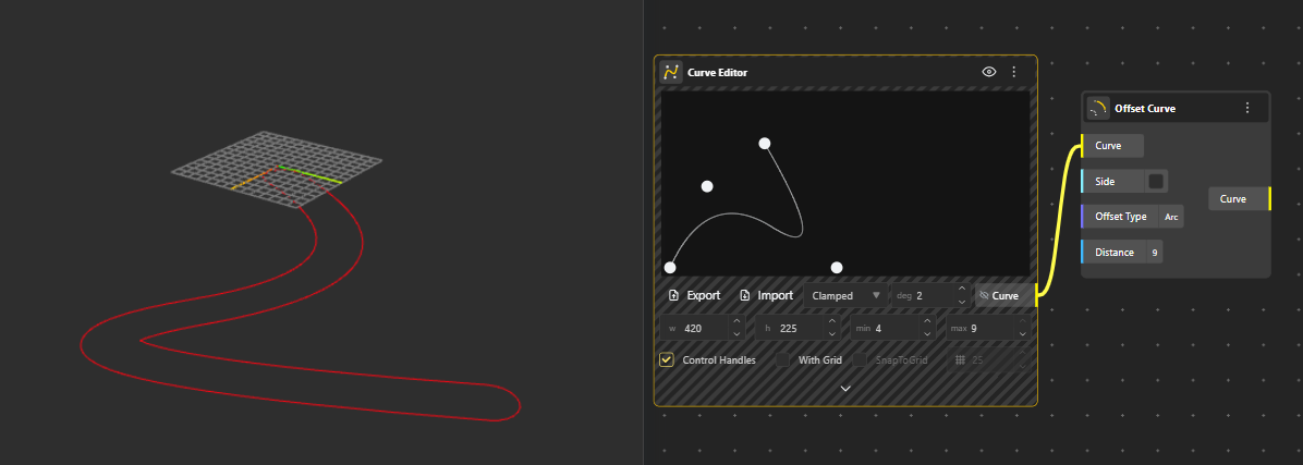
The Offset Curve tool creates a parallel version of an existing curve at a specified distance. You can offset to either side of the curve by adjusting the distance value, and the result updates dynamically if the original curve changes. This is useful for generating boundaries, profiles, or construction curves that follow the same shape but sit at a controlled separation.
Side (Boolean): Controls whether the offset is generated on one side of the curve or both sides.
Checked (True): Creates the offset on only one side of the curve.
Unchecked (False): Offsets on both sides, effectively creating a full loop around the curve.
The Offset Surface tool produces a new surface that sits at a uniform distance from the original one. The offset can be positive or negative, allowing the surface to shift outward or inward. It is especially helpful for creating thickness, layered surfaces, or structural envelopes that maintain consistent spacing.
Offset Type | Key Feature | Curve Behavior | Surface Behavior |
Arc | Smooth, rounded transition | Parallel curve with arcs | Rounded surface extension |
Intersection | Stops/adjusts at intersections | Curve meets other geometry | Surface edges align with other surfaces |
Tangent | Preserves tangency, smoothness | Curve follows tangent direction | Surface offset preserves tangency |
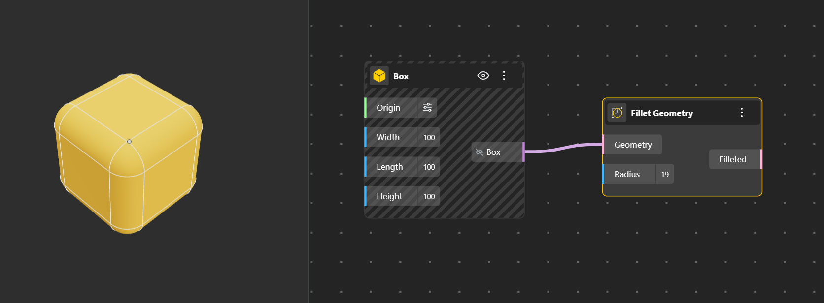
Fillet Geometry Creates a rounded, smooth transition between two edges or curves. Radius input port allows you to define the radius of the Fillet.To clearly see the final result, hide the original geometry so only the filleted output is visible.
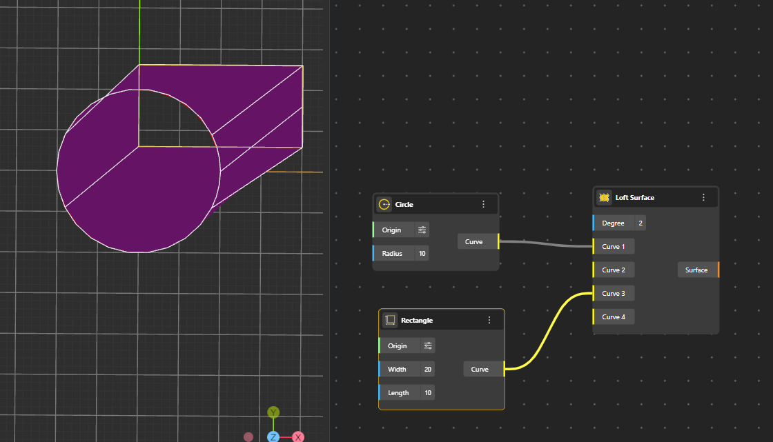
Creates a smooth surface by connecting several curves in order, blending them together into one continuous shape. The overlapping/common areas of the curves are not included in the final surface.
Degree: Controls how smooth or curved the loft becomes when connecting the shapes.
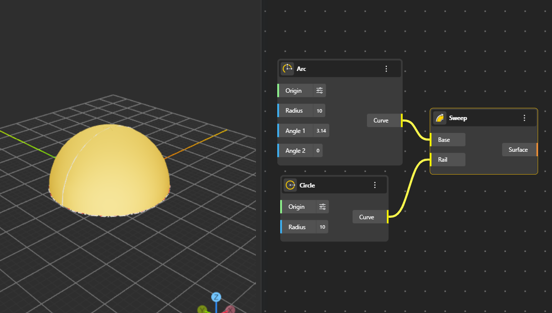
Forms a surface by sweeping a profile curve along a single path curve, ideal for pipes, rails, and smooth transitions.
Base: The shape you want to stretch.
Rail: The path you want to follow.
Example: If the base is an arc and the rail is a circle, the arc moves along the circle and makes a hollow, curved shape like part of a sphere.
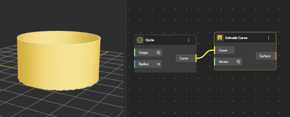
Generates a surface by extruding a curve along a direction or path, producing walls, panels, and linear extensions. You can decide the length and direction of extrusion from Vector port. (By default its In Z direction)
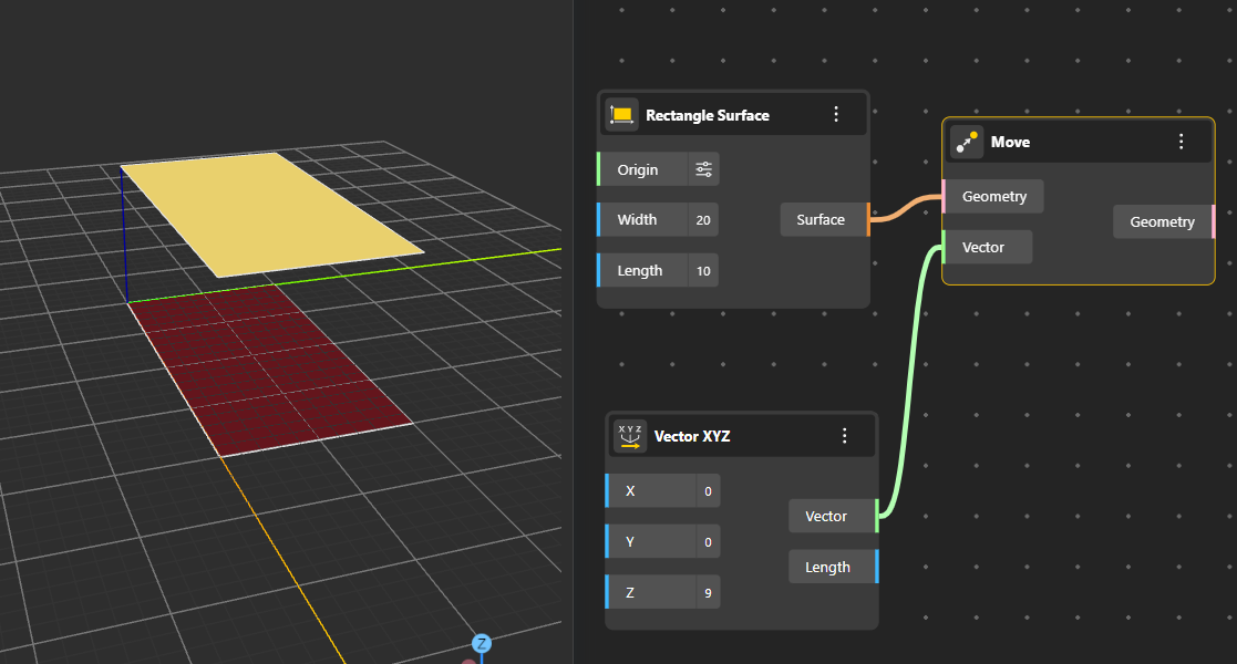
Shifts geometry in space using a defined vector or directional input. Useful for repositioning objects without altering their shape.
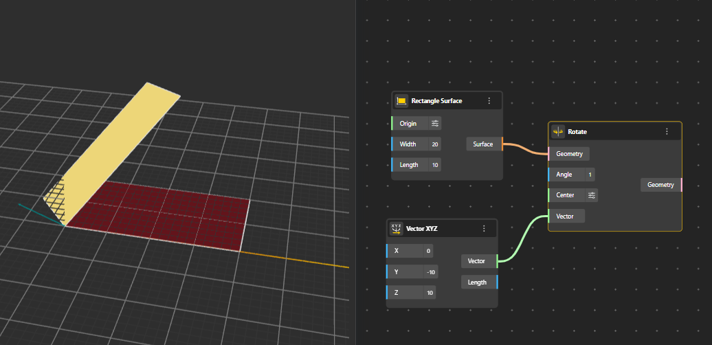
Rotates geometry around a specified axis and angle. The axis can be defined using points, vectors, or a center.
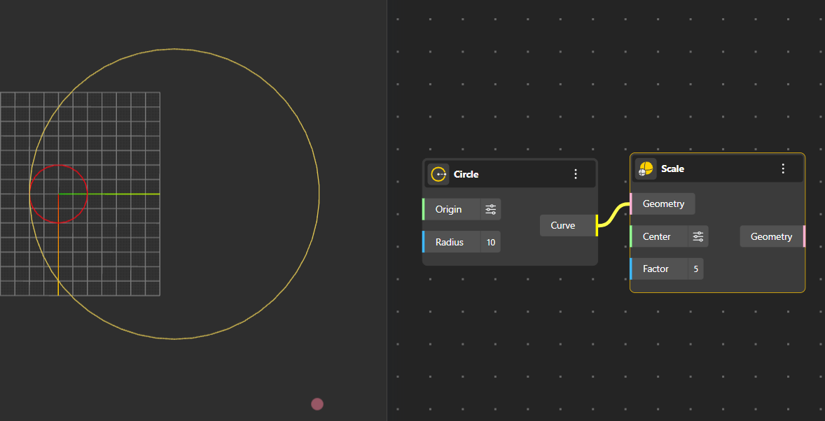
Resizes geometry relative to a chosen origin or center point. Supports uniform scaling across different axes.
Reflects geometry across a selected line, plane, or reference frame, creating a symmetric copy of the original form.
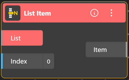
Groups multiple values or geometry objects into a single structured list. This allows you to manage several items together and pass them into another node as one organized input. Lists maintain an ordered index, which is useful when working with sequences of points, curves, or parameters. You can add different types of objects to the same list, and each entry is automatically assigned an index. That index can then be used to retrieve or operate on specific items from the list.
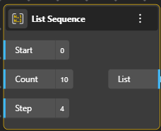
Generates a sequence of values based on three inputs: Start, Step, and Count.
Start defines where the sequence begins.
Step sets how much each next value increases (or decreases).
Count specifies how many values to generate.
The node outputs these values as a list of items, which can then be used to drive parameters, positions, repetitions, or any operation that requires evenly spaced numeric inputs.
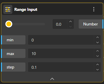
Generates a sequence of numbers within a defined minimum and maximum. You can move a slider across this range to pick any value between them, making it ideal for interactive controls such as moving points, adjusting angles, or modifying dimensions dynamically.
Passes information forward without changing it. It acts like a clean connector to help organize your graph, reduce wire clutter, and redirect outputs neatly when multiple nodes depend on the same data.
Displays the output of any node in a readable text format. It's mainly used for checking values, debugging, or confirming whether the data coming out of a node is what you expect.
Subtracts one or more regions from a base region. It removes the overlapping parts, leaving only the portion of the first region that does not intersect with the others.
Combines multiple regions into a single continuous shape. Any overlapping or touching areas are merged together to form one unified region.
Finds the common overlapping area between two or more regions. Only the shared section where all selected regions overlap is returned.
Boolean Operation Nodes in Tools
Tools that combine, cut, or intersect shapes; letting you merge geometry, remove parts, or keep only the overlapping regions.
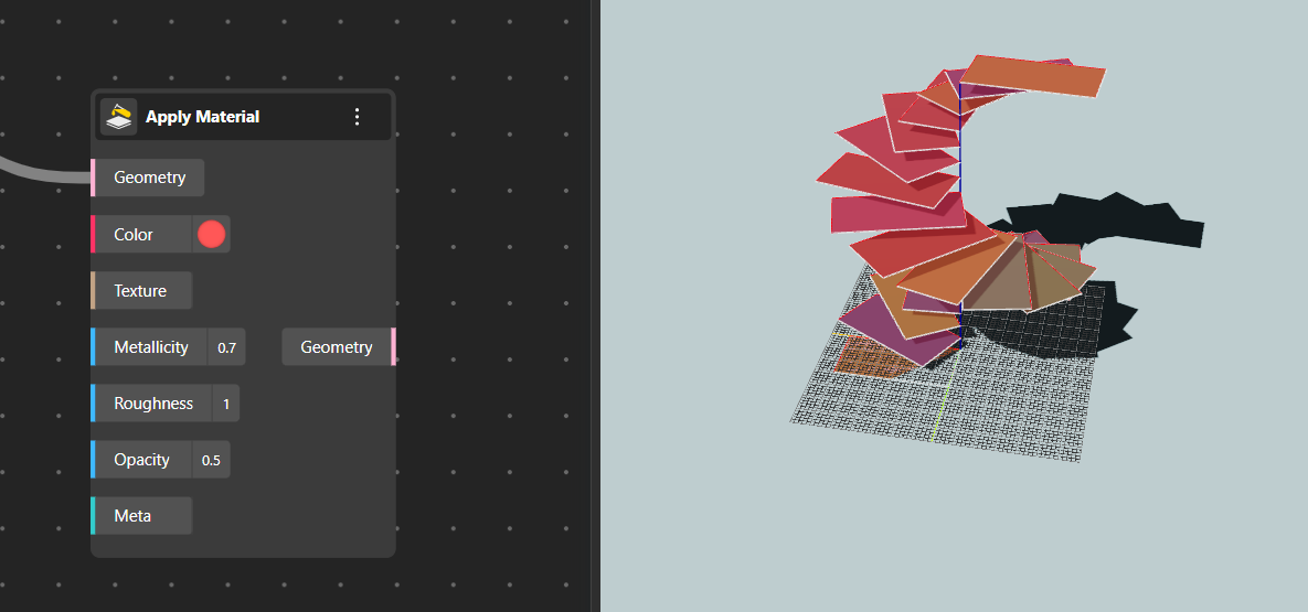
The Apply Material node assigns visual properties to geometry so it appears with color, texture, and physically-based rendering (PBR) attributes in the viewport or final output.
It does not change the geometry itself, only how it looks.
Geometry: The object (curve, surface, solid, mesh, etc.) that you want to apply the material to.
The output will be the same geometry, but with the defined material appearance.
Color: Defines the base color of the material.
Texture: Allows you to plug in an image (texture map) to wrap over the geometry.
Useful for patterns, images, surface details, or realistic materials like wood, concrete, or fabric.
Metallicity: Controls how metallic the surface appears.
0 → completely non-metal (plastic, clay, ceramic).
1 → fully metallic (steel, gold, chrome).
Intermediate values give semi-metallic looks. Higher metallic values make reflections sharper and more mirror-like.
Roughness: Defines how smooth or matte the surface is.
0 → perfectly smooth and glossy (mirror-like).
1 → fully rough and matte (diffused light, no clear reflections).
Adjust this to achieve polished, satin, or rough finishes.
Opacity: Controls transparency.
1 → fully opaque.
0 → completely transparent.
Values in between create glass-like or translucent effects.
You can animate or vary opacity for visual behaviors like fading, layering, or ghosting.
Meta: Optional field used for advanced or custom metadata related to the material. This can include tags, annotations, or information that other systems or plugins might read. Not required for basic usage.